|
 |
|
 |
 |
|
|
|
 |
 |
Modified Rating Life
The modified rating life is calculated by considering lubrication, contaminations and fatigue limit (according to ISO 281:2007(E).
The life Lnm for special bearing properties and for special operating conditions is derived from the following formula for ball
bearings:

| Lnm |
modified rating life [106 revolutions] (the index n
represents the difference between the requisite reliability and 100 %) |
| a1 |
reliability factor for a requisite reliability other than 90 % |
| aISO |
life modification factor for operating conditions |
For a reliability of 90 %, equation 4 takes the following form:

Given a constant bearing rotation speed, it is very often so that the bearing life in operating hours is of particular interest.
For ball bearings:

| Lnmh |
modified rating life [in operating hours] |
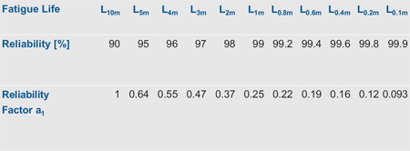
Reliability factor a1
The a1 factor for reliability is used to determine lives other
than the L10m life, i.e. lives which are attained or exceeded with a greater probability than 90 %. Values of
a1 are set out in the Table 3.
Table 3: Reliability factor a1

Variable Bearing Loads and Variable Rotation Speeds
If the load and/or rotation speed for dynamically stressed ball bearings changes in time, this has to be considered when calculating the bearing lifetime. The bearing
lifetime is typically composed of a series of individual loads
[P1,2,...t] and rotation speeds [n1,2,...t] of a certain duration
[q1,2,...t]. This means the bearing is loaded during Period 1 with an dynamic equivalent load P1
and has a rotation speed n1, and so on. For these composite operating conditions, the enhanced adjusted rating life can be calculated
as follows:


L10m1, L10m2, L10m3 ..... can be calculated for ball bearings using Formula 5.
| n1,2,...t |
rotational speed for a particular operation condition [rpm] |
| nm |
mean rotation speed [rpm] |
| q1,2,...t |
duration of a particular operation condition (as a ratio relative to the full period in percent) |
| DPW |
pitch diameter [mm];  |
| d |
bearing bore diameter taken from our product tables |
| D |
bearing bore diameter taken from our product tables |
Life Modification Factor aISO
Among other things, the life adjustment factor aISO considers the influence of:
- fatigue limit of the bearing components’ material by the fatigue load limit Cu
- grade of contaminations by the factor ec and
- lubrication conditions by the viscosity ratio

Fatigue Load Limit Cu
The stress of the raceway fatigue depends primarily on the internal stress distribution at the highly loaded rolling contact point of the bearing. In order to simplify
the calculation, the fatigue load limit Cu was introduced. The fatigue load limit is defined as the load below which no material
fatigue will occur under laboratory conditions.
This factor takes into consideration:
- bearing type, size and internal geometry
- profile of balls and raceways
- manufacturing quality of the bearing
- fatigue limit load of the bearing raceway material
The fatigue load limit Cu for single and double row deep groove ball bearings as well as
single and double row angular contact ball bearings, are listed in the product tables
for all our bearing types.
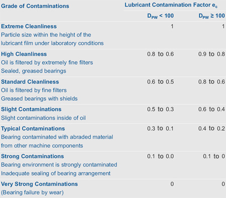
Lubricant Contamination Factor ec
The factor ec considers the influence of contaminants, e.g. solid particles in the lubrication gaps, on the rating life. The lifetime
reduction caused by solid particles depends on their size in comparison to the lubricant film, their hardness and quantity.
Table 4: Lubricant contamination factor ec

More detailed information about the contamination factor ec depending on
 and the bearing size is available in ISO 281:2007(E). and the bearing size is available in ISO 281:2007(E).
Figure 1: Variation of lubricant viscosity as a function of temperature for various mineral oils

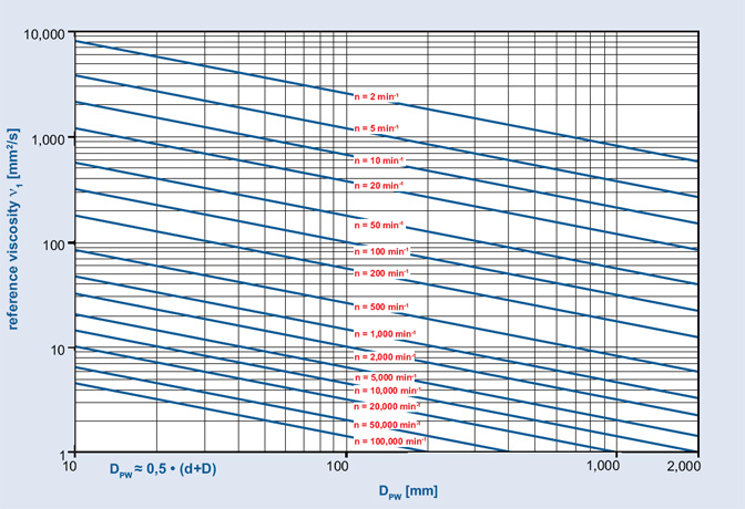
Figure 2: Reference viscosity 

Viscosity Ratio 
The viscosity ratio  acts as an indicator for the quality of the
lubricant film. acts as an indicator for the quality of the
lubricant film.  is the ratio of lubricant viscosity is the ratio of lubricant viscosity
 at operating temperature in relation to the reference viscosity at operating temperature in relation to the reference viscosity
 and it can be calculated using the following equation: and it can be calculated using the following equation:

 |
viscosity ratio |
 |
kinematic viscosity of lubricant at operating temperature taken from Figure 1 for different mineral
oils [mm2/s] |
 |
reference viscosity [mm2/s] |
The base oil viscosity is relevant for greases. Depending on rotation speed n and pitch diameter DPW
of the ball bearing, the reference viscosity  can set off Figure 2. can set off Figure 2.
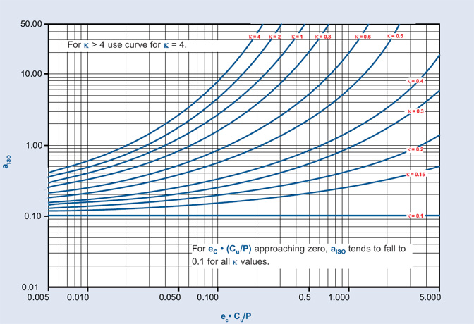
Life Modification Factor aISO
As a function of  the life modification factor aISO
for ball bearings can be read from the Figure 3. the life modification factor aISO
for ball bearings can be read from the Figure 3.
Figure 3: Life modification factor aISO for radial ball bearings according to ISO 281:2007(E)

page up
|
|
|
© 2008-2011 Cixing Group Co., Ltd.
All rights reserved. |
|

